CubicLabs, Inc. In- Vehicle Test, Measurement, and
Control
Equipment
CubicLabs, Inc. In- Vehicle Test, Measurement, and
Control
Equipment
![]()
![]()
For information, please send an email to:
or call:
(734) 426-0872
|
|
|
Multi-Network
Data Acquisition and Control
SenseNET Product Overview
SenseNET’s built in signal conditioning allows direct connection to Analog signals, Digital and State Transition signals, Vehicular Networks such as J1850 and ISO-9141, and a multitude of Sensors, including Thermocouples, Variable Reluctance Sensors, Current Shunts, and Encoders. All input channels are concurrently sampled for all signal types. Cold junction compensation is provided for thermocouple measurements using a built-in precision digital temperature sensor.
Using
SenseNET Software
The power and flexibility of SenseNET hardware may be best understood through a description of the SenseNET software interface and operating modes, including the features of commonly used screens. SenseNET software was developed from the “ground up” to take advantage of the unique features and capabilities of the SenseNET hardware. SenseNET software gives the user complete control over every aspect of SenseNET hardware operation in an intuitive and easy to use series of user interface screens. The user may immediately use SenseNET to “take data” without having to wade through a repetitive series of menus while at the same time preserving their ability to quickly change or add to SenseNET setup information. Functions such as input signal graphing, file save, and posttest analysis are logically grouped to provide convenient operation with the fewest possible keystrokes and button clicks. SenseNET software is engineered to provide quick access to frequently used functions without letting seldom-used features and setup screens get in the way of user productivity.
SenseNET
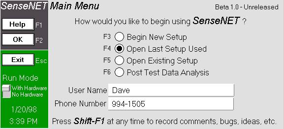
Main Menu
When SenseNET software is run the user will be greeted with the SenseNET Main Menu screen to direct the operating session. “Hot key” support is available to further speed software operation for the novice as well as the experienced user. Operation of software is possible with or without a physical connection to the SenseNET hardware platform. Date and time, Run Mode, and user status information is displayed. A convenient shortcut is provided throughout SenseNET software to allow the user easy access to a report form to record comments, issues, suggestions and request help from the SenseNET support team.
SenseNET
Data Analysis: Files
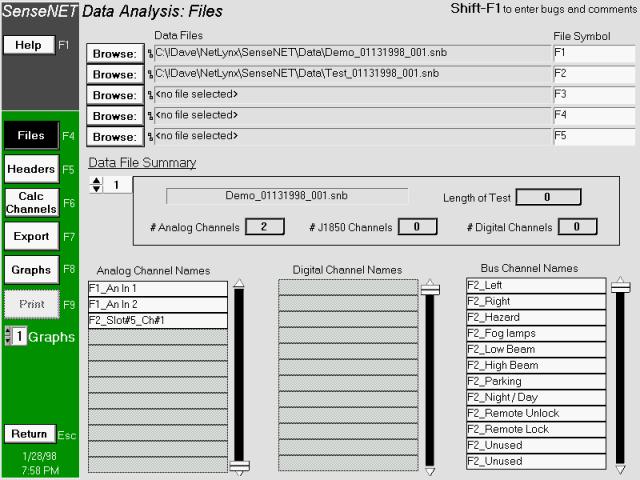
The SenseNET Data Analysis: Files screen provides access to file information and control over user preferences including file naming and location, Analog Channel names, Digital Channel names, Bus Channel names, and file symbol assignments. A comprehensive Data File Summary is provided in the center of the screen which gives the user an “at a glance” overview of the current file setup.
The left-hand side of SenseNET software is typically used to provide rapid, single click access of SenseNET software functions. These Data Analysis function shortcuts include selectors for Files, Headers, Calculated Channels, Data Export, Graphs and Charts, and Printing. A click on the “Return” control gives quick access to the introductory Main Menu screen. SenseNET
SETUP
The setup screen is divided into 11 major sections. Each button on the left side of the screen will display the appropriate section when pressed. The setup is designed to allow the user to setup only the options that are relevant to the testing being done. A logical order of screens is to start at the top and work down through the eleven sections. The software is designed to allow the user to “jump” from any section to any other section in the setup.
The following sections detail the operation of the setup options for all 11 major sections of the setup.
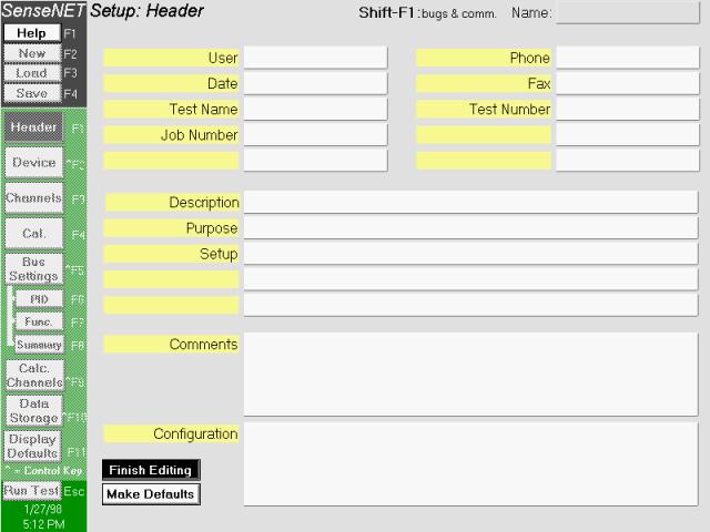
Header
This section contains seventeen user-definable header sections that allow tests to be associated with items such as operator, test number, test description, etc. To define these header fields, simply click on the “Edit Fields” button. All field names may then be edited to display desired header fields. If less than 17 fields are desired for a test, then simply leave the field blank and the white entry field next to the definition field will disappear. To make the displayed fields default, press the “Make Defaults” button after you have named the fields. Please note that pressing the Make Defaults button makes the field names AND the data default. When a “New” setup is selected, the default values will appear in the header section.
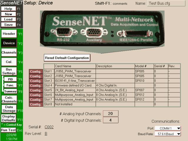
Device
Use the device section to configure the SenseNET hardware. There are 8 plug-in slots in the SenseNET backplane. To query the hardware for the settings, make sure the SenseNET hardware is powered and cabled properly, and press the “Read Default Configuration” button. This will display the hardware configuration with names, descriptions, model numbers, serial numbers, and revision numbers for every card found. The bottom of the screen will also display the serial number and revision level of the SenseNET motherboard. The total number of analog and digital channels is shown at the bottom of the screen.
To configure each individual analog input or digital input card, press the red “Config.” button next to the slot number. Card configuration allows the user to setup the card mode, individual channel settings, and per-channel gains. Please see the following section for detailed information on card configuration.
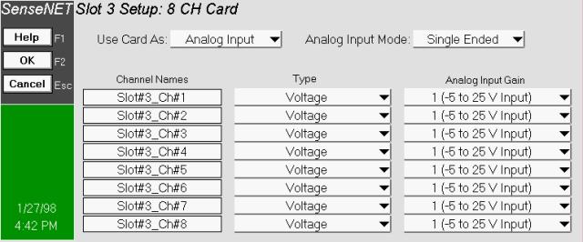
Card
Configuration
Several configuration options are available for input boards. There are different setup options depending on the particular model of input card. Channel names can be changed for any card (they may also be changed on the “Channel Setup” screen). Analog Input Cards
Some cards are available in differential OR single ended mode. If either mode is possible, use the “Use Card As:” pull-down menu to select the mode. Differential mode will cut the number of available channels in half, but is required for signal sources that each have their own ground. Select the type for each channel. Options are: Voltage, current, and thermocouple. Some cards allow user-selectable gains (1,2,4,8). Digital Input Cards
Select the type of digital input. Options are: state, frequency, period, and duty cycle. The user may also adjust the threshold and hysteresis for each individual channel.
Channels
This screen lists all analog and digital channels available in the hardware. Use this screen to select individual sampling rates for each channel. The channel description for each channel gives the channel configuration as well as the pin numbers to which the signals connect. Only the channels “activated” on this screen will show up in subsequent screens (such as Calibration).
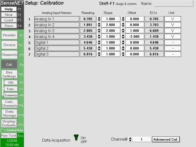
Calibration
Use this screen to assign calibration slope and offsets to any analog or digital input channel. If a SenseNET box is connected to the computer, you may use the switch on the bottom of the screen to turn data acquisition on. This will show the actual input values for each channel. The “Reading” column may also be typed in directly. Please note that only channels that are activated from the “Channels” screen will be displayed on this screen.
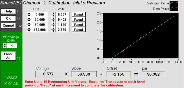
Advanced
Calibration
Use this screen to calculate slope and offset for any channel. Simply select how many readings you would like to take, enter the values you plan to excite the transducer to, then either type the voltages in directly or excite the transducer to each engineering unit level and press the “Read” button. The voltage, slope, offset, and calibrated reading are shown at the bottom of the screen.
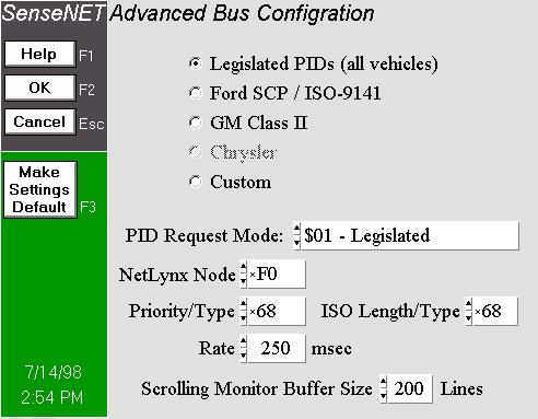
Advanced Bus
Configuration
Use this screen to select the vehicle bus access method and options that you wish to use with SenseNET. The Legislated PIDs selection supports all vehicle manufacturers using the legislated PID access method. Database support for the 32 Legislated messages and parameters will be automatically supplied by SenseNET software without having to import a manufacturer-specific proprietary database. Alternately, manufacturer-specific bus access and database support may be selected. These options require that the user import the specific manufacturer’s database for the vehicle bus (see Import Database in the Bus Settings menu).
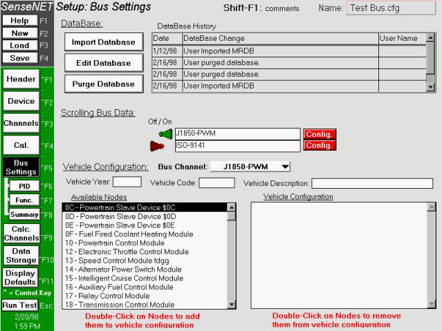
Bus Settings
This screen is divided into two sections. The first is a database import and edit utility. Use this section to import the Ford MRDB database into the SenseNET software. You will need to do this if any bus data will be taken. Please note that importing MRDB overwrites any data that was previously stored in the database. The second section is a vehicle setup section. This section needs to be filled out ONLY if PID data will be taken during the test. To configure a vehicle for PID data requests, simply double-click on the modules (nodes) that are present in the vehicle. Make sure the correct bus channel is selected before adding modules. If you make a mistake, just double-click the incorrect the module and it will be removed. Each vehicle bus protocol interface card available in the SenseNET hardware will be displayed in the center of the screen. Toggle the switch next to each bus to activate scrolling bus data during the run/test screen. Press the "Config." button next to the bus to set up bus transmissions.
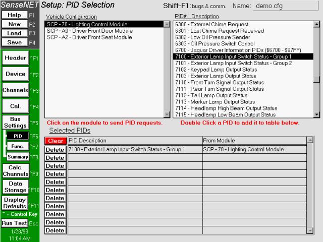
PID Messages
To configure PID requests, first select the module to direct the request to, then double click the PID to request. The selected PID will appear in the table at the bottom of the screen. To see a summary of the PID messages selected, go to the “Bus Summary” section.
Functional
Messages
Use this setup screen to monitor functional “down-the-road” messages while the vehicle is in operation. To configure the software for functional messages, start by clicking on the primary ID. All corresponding secondary ID’s stored in the database will then appear in the “Secondary ID” table. Double-click on the secondary ID to have it appear in the table at the bottom of the screen. Make sure the correct bus is selected before adding functional messages. To see a summary of the functional messages selected, go to the “Bus Summary” section. NOTE:
the “Vehicle Configuration” section of the Bus Settings screen does NOT
need to be set up for functional messages to work properly.
Bus Summary
This screen shows a summary of all bus channels selected. The first three tables break all selected PIDs into numeric, bit mapped, and state encoded parameters. Keep in mind that one PID selection may turn into several channels on the summary screen. Functional parameters are shown in the last table on the screen. Please enter sensible abbreviations in the right-hand columns of the summaries. These abbreviations will be used in all channel pull-down menus in the run time and posttest screens. NOTE:
the abbreviations entered in this screen will be saved in the internal
database until a new database is imported.
This saves the user the trouble of entering an abbreviation every time
a bus channel is used.
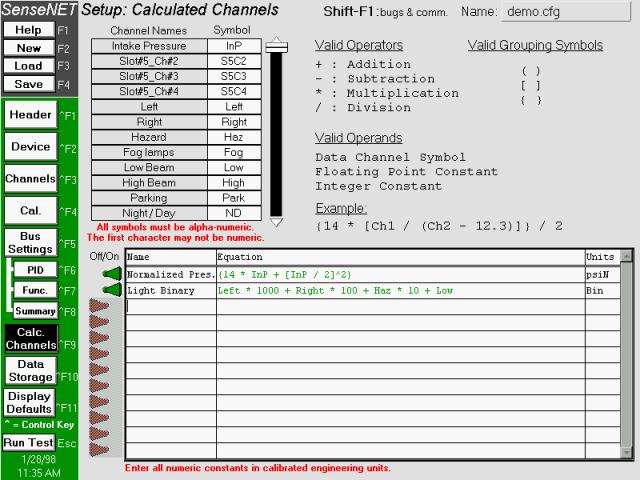
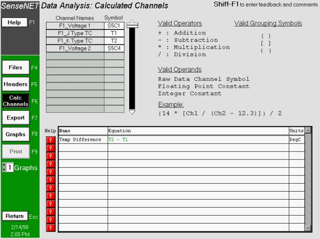
Calculated
Channels
Use this screen to generate calculated channels for the test. All analog, digital, and bus channels are assigned a unique symbol. Use these symbols to generate any desired equation. Any symbols may be changed, but make sure there are no duplicates. All symbols must be alphanumeric and start with a letter (one exception is the “underscore” character). Symbols ARE case sensitive. To enter equations, follow these steps: 1. Enter an equation name. A name of less than 15 characters will fit best into the pull-down menus. 2. Type in the equation. Make sure all symbols used match the symbol list at the top of the screen. 3. Enter the units for the calculated channel. If the equation is valid, the equation will turn green and the toggle switch next to the equation will automatically turn ON. If the equation is invalid, the equation will turn red, a message will pop up telling the user what the problem is and the toggle switch will turn OFF.
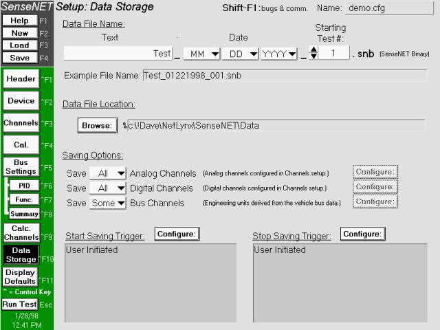
Data Storage
This screen is used to configure saving options during the test. Configure the name of the file at the top of the screen. Each time a file is stored from the run/test screen, the test number will increment by one (1). This prevents the user from needing to enter the setup every time a test is run.
The saving options allow the user to select individual channels for storage. The channels are broken down into analog, digital, and bus channels. For each of these sections select either save all, save none, or save some of the channels. If “save some” is selected, press the configure button to the right of the channel. This will bring up the screen shown on the following page.
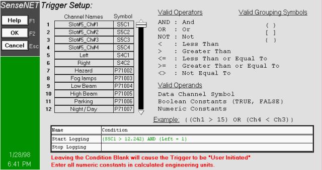
To configure triggering options, press the “configure” button next to the start or stop saving sections. This will bring up a trigger editor that allow the user to type in complicated triggering schemes for starting and stopping tests:
Display
Defaults
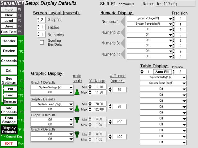
This section simply allows the user to set the default “look” of the run time screen. The run/test screen can accommodate graphs and tables. The total number of graphs and tables can be from 1 to 4 in any combination. Graphs can hold up to 2 channels each, tables can hold up to 12 channel displays each. Regardless of the display defaults, the run/test screen is configurable during the test. Press the “Auto Fill” button to automatically fill in the default display tables with all available channels.
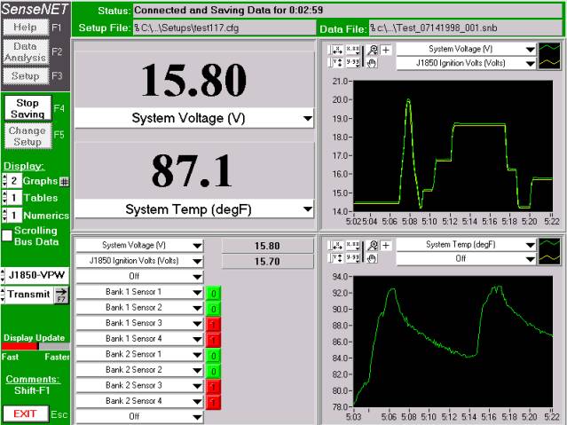
Run/Test
Screen
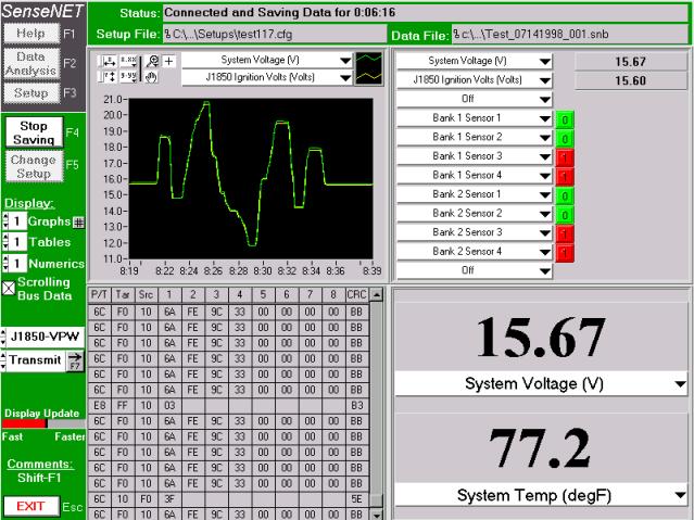
Upon entering the run/test screen, the software will automatically begin to communicate with the hardware. If no hardware is present, the SenseNET software will continuously poll for the hardware until the user exits the screen, or until the SenseNET hardware is connected and powered properly.
The user may at any time adjust the number or type of screen displays. The displayed channels may also be adjusted while the test is running. To begin saving data to file, press the F4 function key or click on the “Start Saving” button. Upon leaving the run/test screen, the SenseNET hardware is reset and any data files that were saved are compiled. The user may elect to change setups at any time by pressing the F5 function key or clicking on the “Change Setup” button. Doing this will reconfigure the screen and the hardware with the new setup information.
Post Test
Data Screen
Use this utility to view data files, convert files to ASCII, export graphical data to files, and print data reports. The screen is divided into 5 separate sections.
Files
Section
This section allows the user to select up to five files to analyze simultaneously. To select files, simply click on the “Browse” button next to an open data file slot. As more files are selected, the channel summaries at the bottom of the screen show the channels that were saved during the test. A file prefix is added to each channel so it is clear which file the channels came from. The data file summary in the center of the screen gives a brief overview of channel counts and length of the test.
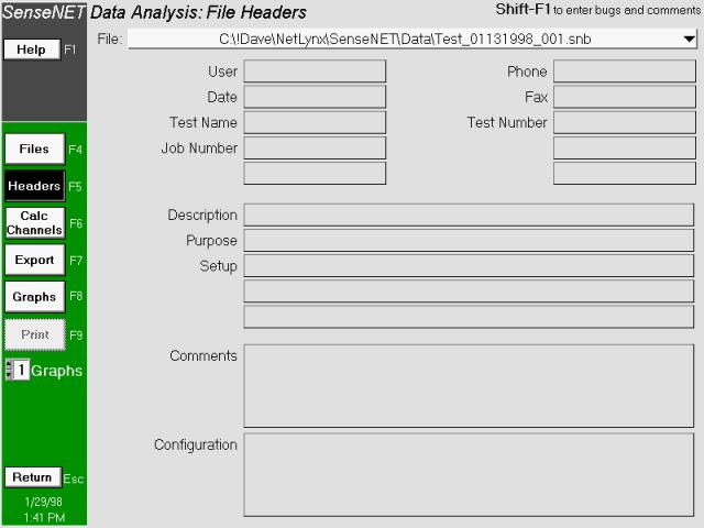
Headers
Section
This screen shows the header information for any file selected in the files screen. To display a header, use the pull-down menu at the top of the screen and select the desired file.
Calculated
Channels
This screen works similar to the calculated channels screen in the setup screen. Calculated channels that were setup pre-test will show up on the table for all selected files. The user may then elect to add more calculated channels.
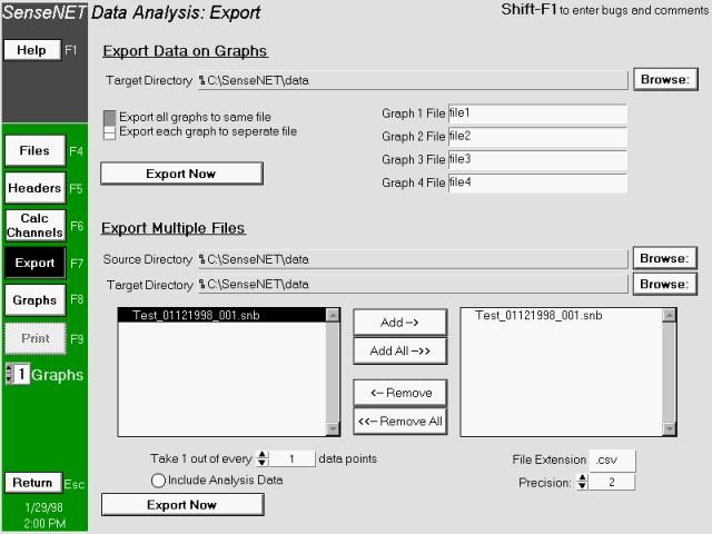
Export Data
This utility is used to export SenseNET binary files to tab-delimited ASCII files. To distinct methods for doing this are available. The first is to export only the data currently being shown on the graphs. To do this, choose a source directory, decide whether each graph will be it’s own file, name the appropriate file(s) and press the Export now button.
The other method of file conversion involves exporting the entire contents of a SenseNET binary file. Multiple files may be chosen for conversion by selecting a source directory and then “Adding” multiple files to the list box on the right side of the screen. Before clicking the “Export Now” button, make sure to select the precision, decimation, file extension and whether analysis data should be included in the file.
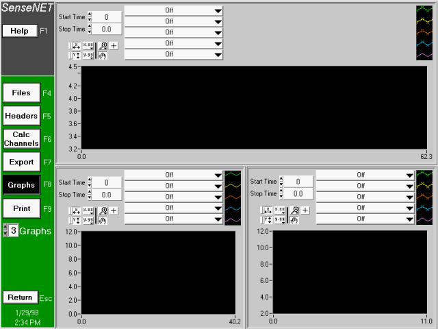
Graphs
Select the number of graphs to show on the screen. Each graph is capable of displaying up to five channels each. All channels from all files selected are available to plot on any graph. The total time displayed on the graph is the time for the “longest” channel currently displayed on the graph.
Press the “Print” button to print the graphic display.
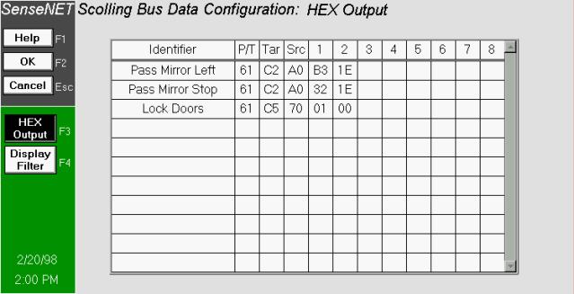
Bus Output
To transmit raw bus messages to the vehicle bus, type in an identifier up to 16 characters in length. The press the tab key and add the raw data to be sent. Each message will appear in a pull-down menu on the test screen. To transmit the message, simply pull-down to the desired message and it will transmit to the bus.
Editing the
SenseNET database
Press the "Edit Database" button to enter the database-editing feature of SenseNET. Use this to add, delete, or modify the J1850 database.
Editing
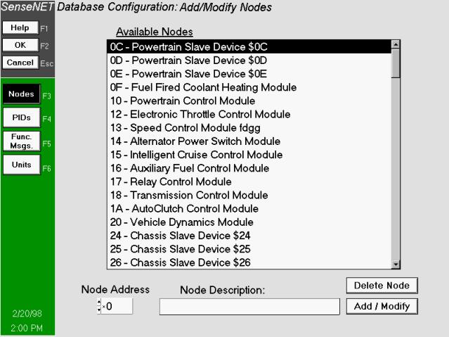
Vehicle Nodes
Use this screen to edit the list of available vehicle nodes. As available nodes are clicked on, the node address and description will automatically be displayed in the editing section of the screen. Make any modifications here and press the "ADD/MODIFY" button. If the node exists, it will modify the description. If the node doesn't exist, then it will add it to the list along with the description.
Edit
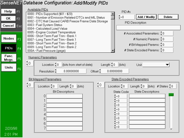
Database: PIDs
Select the PID to modify or type in a new PID number. If you click on a PID all appropriate information on the screen will fill in. All associated parameters, locations, lengths and descriptions will fill in the lists on the screen. Make any modifications and press the add/modify button.
Edit
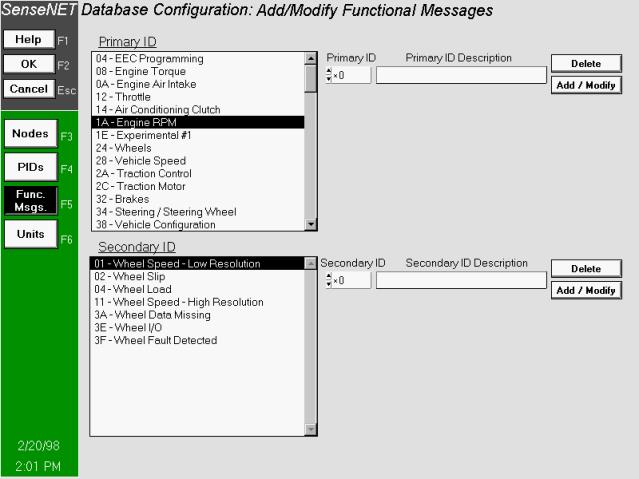
Database: Functional Messages
Edit or add Primary and Secondary IDs as desired and press the "Add/Modify" button. This allows functional messages to be added, deleted or modified in the internal SenseNET database. As the user clicks on various Primary IDs, the appropriate secondary IDs will fill in and be available for modification. More features on functional "down-the-road" messages will be available in the near future.
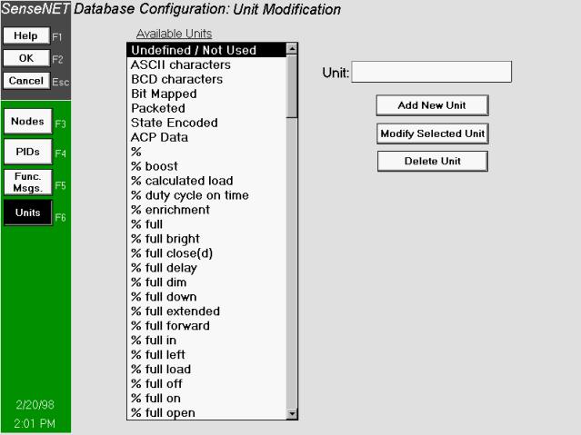
Edit
Database: Units Modification
Use this screen to edit unit descriptions in the database. Units are assigned to numeric bus messages in the "PIDs" screen. The user may select to edit existing unit descriptions or add new units to the list.
|
|
Send mail to
webmaster@CubicLabs.com with
questions or comments about this web site.
|