CubicLabs, Inc. In- Vehicle Test, Measurement, and
Control
Equipment
CubicLabs, Inc. In- Vehicle Test, Measurement, and
Control
Equipment
![]()
![]()
For information, please send an email to:
or call:
(734) 426-0872
|
|
|
NC1 and NC1Config User’s Guide
Customizable Electronics for Test, Measurement and Control NC1Config User’s Guide ã2002 CubicLabs www.CubicLabs.com 139 Dino Drive • Ann Arbor, MI 48103 Phone 734.426.0872 • Fax 734.426.0871
Connecting the NC1 to the Vehicle’s Data Bus and Power NC1Config Software and Database Installation Using the NC1Config Software With and Without the NC1 Description of NC1Config Database Record Fields Index, Length, and Storage Type Output Scale and Output Offset Display Scale and Display Offset Connecting the NC1Config Software to an NC1 To connect the NC1Config software to an NC1: NC1 Output Channel Configurations Automatic Reloading of the Current Configuration from the Saved Configuration at Power-On Changing the Current Configuration of an Output Channel Configuring an Output Channel Using the Database Creating a Database Record from Output Channel Data Levels for Frequency/Pulse Output Signals NC1Config Operational Description Introduction to Obtaining Vehicle Data through a Vehicle Data Bus Multiple output channels process Data from a single message Factors that Effect NC1 Output Signals Variable Frequency PWM Signal with a Fixed Duty Cycle Variable Period PWM Signal with a Fixed Duty Cycle Variable Duty Cycle PWM Signal with a Fixed Period Variable Frequency PWM Signal with a Fixed Pulse Width Variable Period PWM Signal with a Fixed Pulse Width Detailed Description of NC1Config Database Record Fields Output Mode for Frequency/Pulse Type Signals Specifying the Fixed Duty Cycle for Types 2 and 3 Specifying the Fixed Period for Type 4 Specifying the Fixed Pulse Width for Types 5 and 6 Format for the Display of Received Data in an Output Channel icon Processing of SRD by Analog Output Channels Processing of SRD by Frequency/Pulse Output Channels Variable Frequency with a Fixed Duty Cycle or Fixed Pulse Width Variable Period with a Fixed Duty Cycle or Fixed Pulse Width Variable Duty Cycle with a Fixed Period Calculating Scale and Offset Values General Scale and Offset Calculations Calculating Output Scale and Offset Values for Analog Output Signals Calculating Output Scale and Offset Values for Frequency/Pulse Output Signals Calculating Output Scale and Offset Values for the NC1 Display Adding, Editing, and Deleting Records in the NC1Config Database Add New Record to the NC1Config Database Edit a Record of the NC1Config Database Delete a Record from the NC1Config Database
NC1 Product Introduction
The NC1 is an electronic module that can be quickly configured to generate analog and/or frequency/pulse output signals that are proportional to many typical vehicle characteristics based on a single connection to the vehicle’s diagnostic connector. The NC1 provides pseudo sensor signals of vehicle characteristics from data acquired from a vehicle’s data bus (e.g., CAN, ISO-9141, Keyword 2000, J1850 VPW, J1850 PWM, SW-CAN, J1939, etc.).
The NC1 is also able to generate signals proportional to data internal to a vehicle’s electronic modules. Typically this type of data is not available for monitoring or recording at all except through very expensive equipment that is connected to the internal signals of a specially prepared version of a given electronic module. Through the vehicle data bus, the NC1 can obtain such data from any vehicle module accessible through the same vehicle data bus that is used for vehicle diagnostics.
Through the NC1, vehicle data contained in normally occurring messages used to the operation of the vehicle and/or available through diagnostic protocols can be monitored, converted, used to generate scaled analog and/or frequency/pulse, and/or displayed. Every NC1 output channel is completely and independently configured. Each data received and processed has two independent sets of scaling parameters, one to control the output signal and the other to format the data for real time display on a PC.
Once the output channels of an NC1 are configured through the use of supplied NC1Config software, connection to a PC is not required for NC1 operation. This software may also be used to for a real time display of scaled vehicle data. The NC1Config configuring and monitoring software runs on any PC that is using Windows XP, ME, NT 4.0, 98, or Windows 2000.
A 5 digit Ultrabright 7 segment LED display is available on the NC1 as a configurable output channel for the display of vehicle parameter. The NC1Config’s operation is completely configurable through the use of NC1Config software and a configuration database. Through this software and database a user can quickly change the configuration of any and all output channels, monitor in real time the operation of each output channel, and/or create or edit members of the configuration database. Once configured, a NC1 operates autonomously, generating output signals without any need for a connection to a PC.
Some of the parameters of NC1 output channel configurations include the type of vehicle data bus to use, the type of output signal to generate, identifying information for the vehicle data bus message that contains data used to define the current value of the output signal, the definition of a message that may be needed to request the desired data, scaling information for translating the raw data received from the data bus into a proportional output channel signal, and separate scaling information for translating the data for display on a PC.
A predefined set of NC1 output channel configurations based on standard vehicle data legislatively required on all new vehicles is included to assist the user’s initial use of the NC1.
NC1 Operation
The NC1 generates analog and/or frequency/pulse output signals that are proportional to vehicle data the NC1 acquires from a vehicle’s data bus.
The NC1 uses a connection to the vehicle’s diagnostic connector to obtain access to the vehicle’s data bus and to obtain the power it needs to operate and to create the output signals. A serial connection to a PC is used when configuring the NC1’s output channels and/or to monitor the vehicle data being processed by the NC1.
Once its output channels and display are configured, the operation of the NC1 is automatic. Whenever the NC1 is connected to vehicle power, it loads the configuration information last saved in its non-volatile memory, and begins processing data and generating output signals. As the NC1 receives data from the data bus, it creates scaled analog or frequency/pulse output signals based on the received data. The NC1 Display displays selected data. Whenever the data associated with an output channel is unavailable, a channel specific default output signal value is generated.
Connecting the NC1 to the Vehicle’s Data Bus and Power
The NC1 receives its access to the vehicle’s data bus and power through a connection to the vehicle’s diagnostic connector. A Cubic Labs Vehicle Diagnostic cable is used to connect the NC1 to the vehicle’s standard Diagnostic Connector (i.e., SAE J1962). The other end of this cable is connected to the back of the NC1.
Note, to avoid possible problems, the Vehicle Diagnostic cable must be connected to the NC1 first and the vehicle’s diagnostic connector second.
Vehicle Diagnostic Connector
The SAE J1962 Vehicle Diagnostic Connector is required on all new vehicles sold in the USA after model year 1995 (for more information see SAE J1962 Diagnostic Connector). It may also be available on a few model year 94 and 95 vehicles sold in the USA. Tentatively, it will also be required on all new vehicles sold in the EC in calendar year 2000 and later. Different vehicle manufacturers may give different names to the vehicle’s diagnostic connector. Some may call it the ALDL connector, the Class 2 connector, the SCP connector, the 16 way, the J1850 connector, the diagnostic connector, etc.
The vehicle’s diagnostic connector is typically mounted under the instrument panel on the driver’s side of the vehicle. In some vehicles it is located in or near a center console. In some vehicles it is mounted under the instrument panel on the passenger’s side of the vehicle.
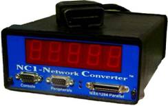
NC1 LEDs
There are two LEDs on the center the NC1’s front panel, mounted vertically, one on top of the other.
The top LED is the power indicator. It will blink when the NC1 is properly powered.
The bottom LED is an error indicator. It will be on if any errors are detected while the NC1 is powered. If any output channel does not receive data within a channel specific timeout period (e.g., when the ignition is off), a channel specific default value will become the current output signal value and the bottom LED on the front of the NC1will be turned on.
In normal operation (i.e., ignition is on), the top LED should be blinking and the bottom LED should be off.
NC1 Output Connections
Several types of standard cables are available for providing output signals from the NC1. NC1 Display
The NC1 Display is a 5-digit Ultrabright 7-segment display mounted on the front of the NC1Config. It can be used to display the same data being processed by one of the NC1Config’s output channels or some other vehicle data value.
The NC1 Display is configured the same way the other NC1 output channels are configured. In this case, instead of generating an output signal its output is the display. The range of displayed values is: –9999 to 0 to 99999. A configuration option for the NC1 Display is the ability to turn on a decimal point on the display. This option can help users to better recognize the data being displayed.
NC1Config Software and Database NC1Config Software and Database Installation
The NC1Config CD ROM contains a copy of the NC1Config software and a copy of a starter NC1Config Database (i.e., NC1Config.mdb).
To install the NC1Config software and the NC1Config Database, use the following procedure.
Place CD ROM in your CD ROM or DVD drive.
Select Run from the Start Menu.
Browse to and run the file named “Setup.exe”.
Using the NC1Config Software With and Without the NC1
The NC1Config software can be used without a connection to an NC1 to review or modify the NC1Config Database.
In order to change the configuration of the output channels on an NC1, the NC1 software must be connected to an NC1 that at least has a connection to power.
To use the NC1 software to monitor active vehicle data, the NC1 software must be must be connected to an NC1 that is powered and connected to an active vehicle data bus (i.e., with the ignition turned on).
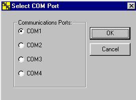
NC1Config Software Start Up
Start the NC1Config software program. NC1Config software will display the following Com Port Selection Screen the first time it is run:
After the COM Port has been successfully selected, the NC1Config software automatically displays the system connect buttons at the bottom of its opening screen (See next page).
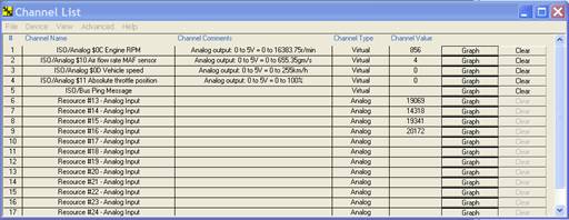
The Channel List Window is shown above as seen when NC1Config software is connected with the NC1 hardware. Note: You do not need to be connected to the NC1Config hardware in order to view the NC1Config database.
The NC1Config Database
Select “Database” from the “View” menu:
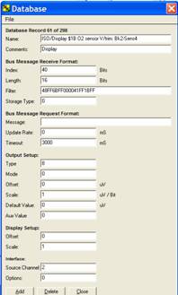
The NC1Config software loads the database and displays the first database record.
Four tape recorder style icons may be used (shown from left to right respectively in the picture above) to select the first record, the previous record, the next record, or the last record of the NC1Config Database. Description of NC1Config Database Record Fields
Each record of the NC1Config Database has 19 fields. The following briefly describes each of these fields. More details about these fields can be found in a later section of this document.
Record Name
Each record of the NC1Config Database has a Record Name field. Typically the contents of this field are used to identify something about the configuration (e.g., the name or type of data being processed, anything that may help identify a special version of a data value, etc. (e.g., RPM, MPH, etc.). The configuration records in the database are presented in Record Name field order.
Comments
Like the Record Name field, the contents of the Comments field of a configuration are used to help the user understand something about the data being processed by a configuration. Generally, the Comments field shows the general signal to data conversion supported by the configuration (e.g., 0v = 0 psi, 5v = 100 psi , 0Hz = 0 6,000Hz = 6,000 RPM, etc.).
Like the Name field, when a Read Current Values option is selected, the Output Channel icons that are created will show the first part of the Comments field of the configuration that is being used by the channel.
Index, Length, and Storage Type
These fields specify where in a received message the desired data begins, the size of the data, and how the data is to be interpreted.
Filter
The Filter field specifies the information to be used to identify messages received by the NC1 from the vehicle’s data bus that contain the data that is to be processed an output channel.
Message
This field specifies a message that is to be sent by the NC1 on the vehicle’s data bus at the rate specified by Update Rate parameter.
Update Rate
If a message must be sent to the vehicle’s data bus in order to have a module send the message that will contain the data to be processed by a configuration, then this field will have a non-zero value that specifies the number of times per second that the request message will sent by the NC1 onto the vehicle’s data bus. If the Update Rate is 0, then no request message will be sent.
Timeout and Default Value
The Timeout field specifies the maximum time, in milliseconds, between messages received for an output channel. If this interval is exceeded without receiving a new message, the value of the Default Value field will be the output channel’s signal value.
Output Type
This field specifies the type of signal generated by the output channel. The values of the Output Type field and the output types they signify are 2= frequency/pulse output signal, 4= analog output signal, and 8 = NC1 Display.
Output Mode and Aux Value
These fields are used to specify which of the available options of the Output Type are to be used.
Output Scale and Output Offset
The contents of these fields are used to scale the received data for generating the output signal for the channel.
Display Scale and Display Offset
The contents of these fields are used to scale the received data for display in a Output Channel icon on a PC. The Output Channel icons are generated when the Read Current Settings option on the Device menu is selected.
Source Channel
This field specifies the type of the vehicle data bus (e.g., 1=J1850 PWM, and 3=J1850 VPW) that the NC1 is to monitor in order to obtain the data to be processed by this configuration. Options
This field is reserved. Its value should be coded as 0.
Connecting the NC1Config Software to an NC1
In order to change the configuration of the output channels of an NC1, the NC1Config software must be connected to a powered NC1.
In order to also display the data being processed by the output channels, the NC1Config software must be connected to an NC1 that is in turn connected to a vehicle’s power and active (i.e., the ignition is on) data bus.
To connect the NC1Config software to an NC1:
1. Ensure the NC1 is connected to a power source. Typically this means the NC1 is connected to a vehicle’s diagnostic connector. A Cubic Labs cable is available to connect the NC1 to a vehicle’s diagnostic connector.
2. Ensure the NC1 is also connected to a serial port on a PC. A Cubic Labs cable is available to connect the NC1 to a PC serial port. One end of this cable must be connected to a connector on the front panel of the NC1. The other end must be connected to a serial port on the PC.
3. Start the NC1Config software if it hasn’t been started yet.
4. If this is the first time NC1 software has been run on your PC, you will be prompted to select which COM Port your NC1Config hardware is connected with. (see below). The Output Channel List for your NC1 will then be displayed.
Channel List
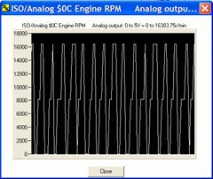
If the NC1Config software can communicate with the NC1, a list of Channels will be displayed on the PC’s screen. There will be one Channel row displayed for each configured output channel in the NC1Config, including the NC1Config Display. Each Channel row will show a channel number. In the example below, the Engine RPM is channel 1. The part of the contents of the Record Name field and the Comment field of the configuration loaded in each output channel will be displayed in the Output Channel row. The Channel Value shows the data being processed in real time by the channel and scaled by the Display Scale and Display Offset values of the configurations loaded in the output channel.
Each Channel row displays: the Record Name field, the Comment field of the record in the NC1Config Database that was used to configure the output channel, The Channel Type and the current Channel Value being received by the indicated channel as scaled by the values in the Display Scale and Display Offset fields. The Graph button will display a scrolling graph of the Channel Value over time. The Clear button reinitializes the entire selected Channel row to “nothing”.
NC1 Output Channel Configurations
Each NC1 output channel has two output channel configurations or settings, the saved configuration and the current configuration. An NC1 output channel processes data from the vehicle data bus based upon the information in the output channel’s current configuration.
Saved configuration data is stored in the NC1’s non-volatile memory. Current configuration data is stored in volatile memory. The current configuration is loaded from the saved configuration when the NC1 is powered up or when the Restore Previously Saved Settings option on the Device menu is selected.
Automatic Reloading of the Current Configuration from the Saved Configuration at Power-On
The current configuration of all output channels is reloaded from their respective saved configurations when the NC1 is powered up.
Changing the Current Configuration of an Output Channel
To change an Output Channel configuration, or to view Output Channel parameters in detail, select a Channel by clicking on the Channel row in the Channel List window. The following Select Network form will appear:
Next, choose the network type you would like to use for the selected channel. The following Output Channel form will appear:
You may now select any of the displayed Output Channel data fields and make changes by highlighting the appropriate text and typing in your changes. When a new configuration is sent to the output channel by using the Modify Output button in an Output Channel form, an attempt is made for the currently displayed NC1Config data to become the new current configuration for the selected output channel. When a configuration is downloaded, a check is made by the NC1 between the values of the fields of the configuration being downloaded and the characteristics of the output channel the configuration is being downloaded to. If the NC1 finds any conflicts, the entire bogus data will be rejected and an error message to that effect displayed by the NC1Config software.
If you wish to make additional changes directly to the Output Channel you have selected, click on the Advanced… button to display the following form:
All of the currently selected Output Channel data items are displayed and may be edited by the user using the same procedure described previously. When you are finished, click on the “Modify Output” button to load your changes into the NC1 hardware. You may click on the “Close Window” button at any time to return to the main software screen.
Configuring an Output Channel Using the Database
You may also configure an NC1 Output Channel using the supplied NC1Config database. The NC1Config database includes all 32 Legislated PID records for each vehicle network that are supported in hardware. The supplied NC1Config database is in Microsoft Access format, and my be added to or edited using the NC1Config software itself.
To change the value of an output channel using the NC1Config software, click on the Channel row to load the Setup window and click on the Drop Box under the “Database Record List” label:
You may scroll down and select any listed NC1Config database record.
After you have selected the database record you are interested in, click on the “Load Output From Database” button.
Creating a Database Record from Output Channel Data
It is often useful to create new Database records from existing Output Channel data. This is most commonly performed to “Clone” multiple NC1 hardware interface devices. A user would typically set up an NC1 hardware configuration, Save all of the Output Channel configurations as database records using the “Save Output to Database” button, and then set up additional NC1 hardware using the “Load Output From Database” function.
Saving NC1 ConfigurationsEven if the NC1 accepts the downloaded configuration, the configuration does not automatically become the saved configuration for the output channel (i.e., it not also put into the output channel’s non-volatile memory). Therefore, if the NC1 had lost and recovered power at this point, the last saved configuration in the output channel’s non-volatile memory would become the current configuration.
To save your current Output Channel configuration, click the “Device” “Save Current Settings” menu item.
Levels for Frequency/Pulse Output Signals
The minimum level for a frequency/pulse signal (i.e., the frequency low value) is 0 VDC.
The maximum level for a frequency/pulse signal (i.e., the digital high value) can be:
· 5 VDC supplied from the NC1’s internal power supply,
· The level of the NC1’s power input, typically a vehicle’s positive battery voltage level, or
· A signal level supplied an external source.
The voltage level of the digital high signal generated by the NC1 is determined by the wiring of one of the output cables plugged into the NC1.
The mating connector on the NC1 includes separate output connector pins that provide access to the NC1’s 5 VDC internal power supply and to the NC1’s power input. This connector also includes an input pin that supplies to all the frequency output channels in an NC1 their digital high signal level. The selection of the level of the digital high output signal is determined by which voltage source, the internal 5 VDC, the NC1’s power input (i.e., from the vehicle), or an external supply, is connected to the input pin that supplies the digital high signal to all the frequency output channels in the NC1.
NC1Config Operational Description
An understanding of the concepts of obtaining vehicle data through a vehicle data bus, scaled received data, and calculating scaling parameters is necessary in order to know the effect of the values selected for the fields of these records and to be able to create or edit records in the NC1Config Database.
Introduction to Obtaining Vehicle Data through a Vehicle Data Bus
Desired data from a vehicle may be available in a message that is always re-occurring on the data bus and/or is available if requested, generally as a response to a diagnostic request message. Since model year 1988, as more vehicle data becomes available through the data buses that are being used in more vehicles, this data can be monitored and/or recorded by accessing it from the data bus through an NC1. When the desired data can be adequately accessed through an NC1, the cost to obtain, store, install, test, remove, and possibly trash traditional monitoring sensors and connecting wires can typically be eliminated. The NC1 can also provide access to data that is created in electronic modules as they go about doing their job, data that is only available from inside the module and not available at all through any add-on sensor.
The data available through a data bus is found in messages that are transmitted and received on the data bus. Two basic types of messages can be found on a vehicle data bus, operational messages and diagnostic messages. Operational messages are messages that are transmitted and received by electronic modules attached to the bus in order for the vehicle to operate properly. These messages normally appear on the data bus on an ongoing basis at a rate that is adequate to support the data availability needs of modules that need the data in order to do their job successfully. Operational messages include only the data that is absolutely necessary for the electronic modules to do their jobs. Diagnostic messages are messages that are used to obtain data that is available through the data bus but is not available or not adequately available in an operational message. Diagnostic messages usually involve a request and response message pair. A diagnostic tool external to the vehicle obtains a connection to the vehicle’s data bus through a diagnostic connector. The diagnostic tool sends a diagnostic request message to the data bus and receives one or more diagnostic response messages from the data bus. Vehicle electronic modules that have a connection to the data bus receive diagnostic request messages, and analyze the request messages to see if the module should respond to it. If an electronic module is responsible for responding to the request message, it does so and typically generates a response diagnostic message. Typically a very very large number of data values can be obtained from a vehicle through diagnostic messages and by comparison relatively few data values are available through operational messages.
In order to know if the NC1 can provide a desired data value and save the cost and time associated with the use of traditional add-on sensors or provide module internal data that is only available through the data bus, one must obtain information about what data is available in operational messages and what data is available through diagnostic messages for a given vehicle. While many data values may be available on most or all vehicles, particularly new models or future models, the actual data available will generally vary from model to model, even within the same manufacturer or product line. Because one model has a data value doesn’t mean another will have it. Likewise, because one model does not have a data value doesn’t mean that another model will not have it. Somewhere in every organization, someone is responsible for knowing and keeping track of the operational messages and the diagnostic messages available on a given vehicle or at least from a given module.
If the desired data is available at an acceptable rate in an operational message then a Filter field must be defined to pass only the specific operational message. The Message field for this database record should be blank and the Update Rate field should be defined as 0.
If the desired data is not normally available at an acceptable rate in an operational message and is available through a diagnostic message then the diagnostic request message must be defined in the Message field, a Update Rate value that is suitable for obtaining the data must be defined, and a Filter to pass only the related diagnostic response message must be defined.
The Filter field tells an NC1 output channel when a message has been received that contains the data to be processed by that channel. Each received message has a header field and a data field. Sometimes the data field is broken down into multiple sub-fields.
The Filter field is one or more two byte sets. Hexadecimal coding is used. The first byte of a set defines the bit by bit data values that must be matched by a received message in order to be passed by the filter and processed by an output channel. The second byte of a set is a mask byte that defines, bit by bit, which bits of a received message byte and the data byte of the set are to be checked for a match. If a bit in a mask has a value of “1”, then bits, in the same position within the byte, in the data byte and the received byte are compared. “0” bits in a mask indicate bits in the data byte and received byte that are not compared.
Filter definitions must be as specific as possible so as to not pass incorrect messages to the output channel. Cubic Labs is available to assist user in defining specific Filter fields.
The Index and Length values define where in a received message that has passed the Filter the desired data starts and how long it is, respectively. The first bit of a received message, the high order bit of the first byte of the message has a Index value of 0. The first/high order bit of the second byte has a value of 8. Length values are typically in multiples of 8 (e.g., 8, 16, 24, 32, etc.). Occasionally, the data is one or a few bits in size. In these cases the Length value would be 1, 2, 3, etc.
The Storage Type value indicates whether the data should be processed as 2’s complement signed data or as unsigned data. Most data is unsigned, but once in a while data is signed. Another way to look at this is to ask if the raw data in the received message can be negative. This does not refer to the scaled value of the data, only to the raw data in the received message.
Received data is multiplied by the value of the Output Scale field and the result of that multiplication is added to the value of the Output Offset field (i.e., y = m * x + b, where x is the received data, m is the Output Scale, b is the Output Offset, and y = the scaled result). The values of Output Scale and Output Offset depend in the resolution of the received data, the range of the scaled data derived from the received data, and the desired range and lowest value of the proportional output signal. See a section on Output Signal and Display Scaling elsewhere in this document for more detailed information, formulas, and examples.
Several configuration parameters are used to indicate the type of output channel that a configuration is for and to specify the output characteristics the Describing the desired type of output channel signal Output Type, Output Mode, and Aux Value
Multiple output channels process Data from a single message
There may be some cases where it is desired to have the same data in the same received message processed by multiple output channels. There may a need to create both an analog signal and a frequency/pulse signal for the same data value. There may be a need to create output signals that have different scaling values.
There may also be cases where there are multiple pieces of data in the same received message that are to be processed by different channels.
As outlined above, when data from a single received message is to be processed by multiple output channels, each channel configuration must have the same Filter field. If a request message must be sent by the NC1 to obtain the data, only one channel configuration should include the Message and Update Rate values required. The other channel configurations that are to also process this same message must have a blank Message field and a Update Rate value of 0.
Factors that Effect NC1 Output Signals
The signal generated by an NC1 output channel is determined by:
· The availability of the desired data, Message, and Update Rate,
· The Filter, received messages, Index, Length, Storage Type, Output Scale, and the Output Offset,
· The output channel model, Output Type, Output Mode, and Aux Value, and
· The time since the last filtered message was received, the Timeout value, and the Default Value.
Frequency Output Signals
The NC1 can generate frequency output signals of a variety of types and a variety of digital high signal voltage levels.
Frequency Output Types
The following outlines the types of frequency/pulse output signals the NC1 can generate.
State
This is a digital signal where the signal level (i.e., digital high or digital low) is determined by the scaled received data. The interval between signal level changes is determined by the interval between the scaled received data values that translate into digital high and digital low signal values.
Variable Frequency PWM Signal with a Fixed Duty Cycle
This is a PWM signal with a fixed duty cycle where the frequency is determined by the scaled received data.
Variable Period PWM Signal with a Fixed Duty Cycle
This a PWM signal with a fixed duty cycle, where the period, that is the length of the PWM signal, is determined by the scaled received data.
Variable Duty Cycle PWM Signal with a Fixed Period
This is a PWM signal with a fixed period, where the duty cycle is determined by the scaled received data.
Variable Frequency PWM Signal with a Fixed Pulse Width
This is a PWM signal with a fixed pulse width, where the frequency is determined by the scaled received data.
Variable Period PWM Signal with a Fixed Pulse Width
This is a PWM signal with a fixed pulse width, where the period of the signal is determined by the scaled received data.
Detailed Description of NC1Config Database Record Fields
Each record of the NC1Config Database has 19 fields. The following describes each of these fields.
Record Name
Each record of the NC1Config Database has a Record Name field. The contents of the Record Name field should be something that is meaningful to the user of the NC1. Typically the contents of this field are used to identify something about the configuration (e.g., the type of data bus, the name of data being processed, output type, etc. (e.g., PWM J1979 DTC Count)).
The Record Name field can be up to 29 characters, including blanks.
When the fields of a record of the NC1Config Database become the configuration for an output channel, the Name field is included. When a Read Current Values option on the Device menu is selected, the Output Channel icons that are created show the first 29 characters, blanks included, of the Record Name field.
Each record of the NC1Config Database must have a unique Record Name field. The records of the database are sorted in alphabetical order by the contents of the Record Name field. The contents of the Record Name field determine which record is shown when a user selects the first record, the next record, the previous record, or the last record of the NC1Config database.
Comments
The contents of the Comments field are saved like the contents of the Record Name field, as part of an output channel’s configuration in an NC1. When Channel rows are listed by the Read Current Settings option on the Device menu of the NC1Config software, the contents of the comments field of each configured output channel are displayed.
One use of this field is to document the general conversion values for the channel (e.g., 0v = 0 psi, 5v = 100 psi).
The maximum size of this field is 39 characters.
Update Rate
This field specifies the number of times per second that a request message for the desired data will be sent by the NC1Config onto the vehicle’s data bus. The request message itself is defined in the Request Message field. If no request message is needed, then the Update Rate should be set to 0.
Note that vehicle manufacturers have limits on the rate at which outside messages can be sent onto the data buses of their vehicles. In some cases this rate may vary from vehicle to vehicle within the same manufacturer and same model year.
The values for the Update Rate range from 0 to 18.
Source Channel
This field specifies the type of the vehicle data bus that the NC1 is to monitor in order to obtain the desired data for the output channel. The values to be used for the Source Channel field and the vehicle data bus types they define are: 1=J1850 PWM, 2=ISO-9141, 3=J1850 VPW, 4=CAN, 7=KW2000, and 9=OBD CAN.
The NC1Config product can support multiple vehicle data bus types. Normally, for a given database, the Source Channel values, that is the type of vehicle data bus, would be the same type for all database records. Index
This field specifies, by bit offset, where in a received message the desired data begins. The first (i.e., high order) bit of the first byte of a message has an Index value of 0. The values for Index range from 0 to 95.
Length
This field specifies, in bits, the length of the desired data in the received message. The values of the Length field can range from 1 to 32 inclusive.
Storage Type
This field specifies the way the data in the received message identified by the Index and Length parameters is to be interpreted relative to the use or non-use of signed value encoding. The values of the Storage Type field and the type of data they represent are 0= unsigned data, and 1= signed data.
Output Scale
This field specifies the value that the received data will be multiplied by as apart of the output scaling process. The result of this multiplication is added with the value of the Output Offset field to complete the scaling process and specify the value for an output channel.
The Output Scale field can be defined with an integer or a floating-point type of value (e.g., 123, 17.45, 3590., etc). The range of the values for this field is +/- 2-31 to +/- 2+31. If the Output Scale field is given a value of 0, then any connection to the data being received is lost.
Output Offset
See the explanation for the Output Scale field. The Output Offset is an integer value. The range of values for the Output Offset field is -231 to +231 (i.e., 2,147,483,647).
Display Scale
This field and the Display Offset field are similar to the Output Scale and Output Offset fields. The difference is that the resultant scaled value is displayed in an Output Channel icon on the screen of a PC using the NC1Config software rather than used to effect the output channel’s signal. These fields are particularly useful when it is meaningful to display the data in a way that is different from the way the value of the associated output channel signal is calculated.
The range of values for this field is the same as for the Output Scale field.
Display Offset
See the explanation for the Display Scale field.
The range of values for this field are the same as for the Output Offset field.
Options
This field is reserved. Its value will usually be coded as 0.
Output Type
This field specifies the type of signal generated by the output channel. The values of the Output Type field and the output types they signify are 2= frequency/pulse output signal, 4= analog output signal, and 8 = NC1 Display.
Message
This field specifies a message that is to be sent by the NC1 on the vehicle’s data bus at the rate specified by Update Rate parameter.
The codes to be used for the Message field are hexadecimal byte values (i.e., 00 to FF). The maximum length is dependent on the type of vehicle data bus (e.g., 12 bytes for J1850) to be used.
Request messages are used to obtain data when the data to be processed by an output channel is not normally available on the vehicle’s data bus but can be obtained by send a request for it.
Filter
The Filter field specifies the information to be used to identify messages received by the NC1 from the vehicle’s data bus that contain the data that is to be processed an output channel.
The coding of the Filter field is hexadecimal byte values.
The Filter field is made up of a series of two-byte sets. The first byte of a set defines bit values that must be matched by corresponding bits in the received message in order to pass through the filter and be processed by the output channel. The second byte of the set is a data mask. The mask specifies which bits of the data byte part of the set are to be compared to the corresponding bits of the corresponding byte in received messages.
The first two-byte set processes the first byte of the received message. The second set processes the second byte of the received message. And so on for as many two byte sets as are needed to uniquely identify the message to be processed from all the messages that may appear on the vehicle’s data bus.
Each message that is received by the NC1 from the vehicle’s data bus is processed by the Filter values of all defined output channels in the NC1. A given message may pass the Filter of multiple output channels.
Timeout
The Timeout field specifies the maximum time, in milliseconds, between messages received for an output channel. If this interval is exceeded without receiving a new message, the value of the Default Value field will be the output channel’s signal value.
The value of this field ranges from 10 to 655356 (i.e., 65.536 seconds) inclusive.
Default Value
See the Timeout field above. The codes to be used for this field range from 0 to +/- 5,000,000 mv inclusive, for a 0 to 5.0 v analog type output channel.
Output Mode
Currently, the Output Mode is only has meaning when the Output Type field specifies a frequency/pulse type output signal (i.e., Output Type = 2).
Output Mode for Frequency/Pulse Type Signals
When the Output Type field specifies a frequency/pulse output (i.e., Output Type = 2), the Output Mode field specifies the type of frequency/pulse signal. The values to be used for the Output Mode field and the types of frequency/pulse outputs they specify are:
· 1 = State, · 2 = Variable Frequency with a Fixed Duty Cycle, · 3 = Variable Period with a Fixed Duty Cycle, · 4 = Variable Duty Cycle with a Fixed Period, · 5 = Variable Frequency with a Fixed Pulse Width, and · 6 = Variable Period with a Fixed Pulse Width.
Aux Value
When the Output Type field specifies a frequency/pulse output, the Aux Value field specifies the fixed duty cycle, period, or pulse width of the signal, depending on the value of the Output Mode field. See the sections below for information on the use of the Aux Value field.
Specifying the Fixed Duty Cycle for Types 2 and 3
For frequency/pulse Output Types with Output Mode values of 2 and 3, the Aux Value defines the fixed duty cycle (i.e., 0 to 100 %).
If Aux Value < 655.35, then the duty cycle = 0 % (i.e., no signal)
If the Aux Value >/= 65535, then the duty cycle = 100 % (i.e., constant digital high signal)
If 0 < Aux Value </= 65535, then the duty cycle = (Aux Value / 65535) * 100 %.
Specifying the Fixed Period for Type 4
For frequency/pulse Output Types with an Output Mode value of 4, the Aux Value specifies the fixed period. The shortest period is 20 ms (i.e., Aux Value = 20) and the longest period is 114,285 ms (i.e., Aux Value = 114,285).
Specifying the Fixed Pulse Width for Types 5 and 6
For frequency/pulse Output Types with Output Mode values of 5 and 6, the Aux Value specifies the fixed pulse width. The smallest pulse width is 20 ms (i.e., Aux Value = 20) and the largest pulse width is 114,285 ms (i.e., Aux Value = 114,285).
Scaled Received Data (SRD)
One of the most important concepts to understand when configuring an NC1output channel is the concept of Scaled Received Data (SRD). The value of output channel signals are based on its SRDs. SRD is the result of scaling data from a received message.
An NC1 output channel configuration includes information that identifies:
The received message that will include the data to be processed for the channel,
Where in the received message the data begins (i.e., Index), what the size of the data is (i.e., Length), and whether the data is to be interpreted as a signed or as an unsigned value (i.e., Storage Type), and
The scale and offset parameters (i.e., Output Scale and Output Offset) that are to be used to calculate the SRD.
The SRD that results from this process is the input to the process that determines the signal generated by the output channel.
The output channel configuration parameters mention above, the receive message filtering process, the scaling process, the output signal generating process, and other associated processes that result in producing SRD and the output signal will be described in further detail below. Where SRD is referenced in this document, it is the result of the scaling process applied to data received from a vehicle data bus message and the value used to determine the characteristics of the signal generated by an output channel.
Another scaling process that uses a separate set of scale and offset parameters (i.e., Display Scale and Display Offset) included in a channel configuration is used to scale the received data for display in an Output Channel icon on a PC screen. The same received message data used to calculate the SRD is used to calculate the data value displayed in the Output Channel icon. These parameters and the data display process will be described in further detail below. The scaling process used here is the same process used to calculate the SRD.
Mathematically, the SRD is interpreted as a 32 bit signed integer value (i.e., a long integer in C). The SRD is the result of multiplying the received data by the Output Scale and adding to the result of the multiplication the Output Offset and then converting the result this addition into an 32 bit signed integer value (i.e., y = m * x + b, where SRD = integer of the y value, where x is the received data, m is the scale value, b is the offset value, and y = the result of the scaling process).
The received data is the data from a message that was received from a vehicle data bus and passed through the Filter defined for an output channel. The Index and Length specify where in the received message the data starts and how long it is. Storage Type specifies whether the received data is interpreted as either a signed or an unsigned value. The Output Scale and Output Offset values may be positive or negative and may be defined in an integer or floating point form (i.e., floating point means defined with a decimal point and with or without fractional values). An SRD may be a positive or a negative value.
The signal generated by an output channel is determined by the SRD’s value and the way a given output channel processes that value. Output Type, Output Mode, and Aux Value determine the way an output channel processes an SRD.
Note that the NC1 Display is an output channel just like an analog or frequency/pulse output channel.
Output channel processing details for analog channels, frequency/pulse channels, and the NC1 Display are described below.
Format for the Display of Received Data in an Output Channel icon
The data displayed in an Output Channel icon uses the same scaling process as is used to calculate the SRD but with the Display Scale and Display Offset values instead of the Output Scale and Output Offset values.
Data displayed in an Output Channel icon is displayed as a signed 32 bit integer (i.e., -231 to +231). Details for calculating Display Scale and Display Offset parameters are shown below.
Processing of SRD by Analog Output Channels
For analog output signals, the SRD is interpreted as a mVDC (i.e., 0.000001 VDC) value. The lowest signal value above 0 is 1 mVDC (i.e., SRD = 1) and the highest signal value is 5,000,000 mVDC (i.e., SRD = 5,000,000).
If SRD < 0, then signal = 0 VDC (i.e., no signal)
If SRD >/= 5,000,000, then signal = 5,000,000 mVDC (i.e., 5.000000 VDC)
If 1 </= SRD </= 5,000,000, then signal = SRD mVDC
Processing of SRD by Frequency/Pulse Output Channels
Each type of frequency/pulse output channel has type specific rules for interpreting and processing SRD values.
State Type
For State type frequency/pulse outputs (i.e., Output Mode = 1), the output signal value is either digital low or digital high, depending on the value of the SRD.
If the SRD is less than or equal 0 (i.e., 0 or any negative signed value), then the output signal is digital low.
If the SRD is greater than 0 (i.e., any non-zero positive value), then the output signal is the digital high.
Variable Frequency with a Fixed Duty Cycle or Fixed Pulse Width
For variable frequency frequency/pulse output signals with a fixed duty cycle or a fixed pulse width (i.e., frequency/pulse type signals with Output Mode values of 2 or 5), the SRD is interpreted as a mHz (i.e., milli-Hertz) value. The lowest frequency above 0 is 8.75 Hz (i.e., SRD = 8750) and the highest frequency is 20,000 Hz (i.e., SRD = 20,000,000).
· If SRD < 8750, then frequency = 0 Hz (i.e., no signal)
· If SRD >/= 20,000,000, then frequency = 20,000,000 mHz (i.e., 20,000 Hz)
· If 8750 </= SRD </= 20,000,000, then frequency = SRD mHz
Variable Period with a Fixed Duty Cycle or Fixed Pulse Width
For variable period frequency/pulse output signals with a fixed duty cycle or a fixed pulse width (i.e., frequency/pulse type signals with Output Mode values of 3 or 6), the SRD is interpreted as a ms (i.e., microsecond) period value. The shortest period above 0 is 20 ms (i.e., SRD = 20) and the longest period is 114,285 ms (i.e., SRD = 114,285).
· If SRD < 20 then period = 0 ms (i.e., no signal)
· If SRD > or = 114,285 then period = 114,285 ms
· If 20 </= SRD </= 114,285 then period = SRD ms
Variable Duty Cycle with a Fixed Period
For variable duty cycle frequency/pulse output signals with a fixed period (i.e., frequency/pulse type signals with an Output Mode value of 4), the SRD is interpreted as duty cycle %. The smallest duty cycle value above 0 depends on the period selected. The shortest pulse width is 20 ms. 20 ms divided by the period in ms is the smallest % above 0 that will generate at least some signal other than a constant low value. The largest duty cycle is 100 % (i.e., SRD >/= 65535).
IF STD < smallest non zero %, then duty cycle = 0 % (i.e., constant digital low signal) Where smallest non zero % = 20 ms / period selected
· If SRD >/= 65535, then duty cycle = 100 % (i.e., constant digital high signal)
· If 0 < SRD </= 65535, then duty cycle = (SRD/65535) * 100 %.
Calculating Scale and Offset Values
General Scale and Offset Calculations
To calculate the scale and offset field values used to create a scaled output signal or a displayed value from the received data, the following formulas can be used.
Where: VH = Highest output channel value (e.g., 5,000,000 mVDC or 20,000,000 mHz)
· VL = Lowest output channel value (e.g., 0 mVDC or 0 mHz)
· DH = Highest scaled data value (e.g., 10,000 RPM)
· DL = Lowest scaled data value (e.g., 0 RPM)
R = Resolution = Scaled data value/bit of received data value (e.g., 0.25 RPM/bit)
· Scale = [(VH - VL)/ (DH – DL)] * R
· Offset = [(- DL)/(R)] * Output Scale
The following sections contain examples of calculating Output Scale and Offset values for analog output signals, digital/pulse output signals, and the NC1Config Display, and calculating of Display Scale and Offset values.
Calculating Output Scale and Offset Values for Analog Output Signals
Example 1
Calculate Output Scale and Offset for an analog output signal with a signal range 0 to 5 VDC being equivalent to an RPM range of 0 to 10,000 RPM, where the resolution of the received data received is 0.25 RPM/bit (i.e., VH = 5,000,000mVDC, VL = 0, DH = 10,000, RPM, DL = 0 RPM, and R = 0.25 RPM/bit):
Output Scale = [(VH - VL)/ (DH – DL)] * R
= [(5,000,000 – 0) / (10,000 – 0)] * 0.25
= [5,000,000 / 10,000] * 0.25
= 500 * 0.25
= 125
Output Offset = [(- DL)/(R)] * Output Scale
= [(-0)/(0.25)] * 125
= 0
Example 2
Create a full range analog output signal (i.e., 0 to 5 VDC) equivalent to a temperature range of –300 °F to +300 °F, where the data received from the vehicle data bus has a resolution of 0.125 °F /bit (i.e., VH = 5,000,000mVDC, VL = 0, DH = +300 °F, DL = -300°F, and R = 0.125 °F/bit
Output Scale = [(VH - VL)/ (DH – DL)] * R
= [(5,000,000 – 0) / (+300 – (-300))] * 0.125
= [5,000,000/600] * 0.125
= 8333.3333 * 0.125
= 1041.6667
Output Offset = [(- DL)/(R)] * Output Scale
= [(-(-300))/(0.125)] * 1041.6667
= 2400 * 1041.6667
= 2,500,000
Calculating Output Scale and Offset Values for Frequency/Pulse Output Signals
Example 1
Calculate Output Scale and Offset for an variable frequency frequency/pulse output signal with a signal range 0 to 10,000 Hz (i.e., 10,000,000 mHz) being equivalent to an RPM range of 0 to 10,000 RPM, where the resolution of the received data received is 0.25 RPM/bit (i.e., VH = 10,000,000 mHz, VL = 0, DH = 10,000, RPM, DL = 0 RPM, and R = 0.25 RPM/bit):
Output Scale = [(VH - VL)/ (DH – DL)] * R
= [(10,000,000 – 0) / (10,000 – 0)] * 0.25
= [10,000,000 / 10,000] * 0.25
= 1,000 * 0.25
= 250
Output Offset = [(- DL)/(R)] * Output Scale
= [(-0)/(0.25)] * 125= 0 Example 2
Create a variable frequency frequency/pulse output signal of from 0 to 600 Hz (i.e., 600,000 mHz) being equivalent to a temperature range of –300 °F to +300 °F, where the data received from the vehicle data bus has a resolution of 0.125 °F /bit (i.e., VH = 600,000 mHz, VL = 0, DH = +300 °F, DL = -300°F, and R = 0.125 °F/bit
Output Scale = [(VH - VL)/ (DH – DL)] * R
= [(600,000 – 0) / (+300 – (-300))] * 0.125
= [600,000/600] * 0.125
= 1000 * 0.125
= 125
Output Offset = [(- DL)/(R)] * Output Scale
= [(-(-300))/(0.125)] * 125
= 2400 * 125
= 300,000
Calculating Output Scale and Offset Values for the NC1 Display
The NC1 Display is another output channel type just like an analog or a frequency/pulse output channel. The data processed by the NC1 Display output channel can be the same data that is being processed by one of the output channels in the NC1 or it can be unique data.
The NC1 Display has an output channel configuration just like the analog or frequency/pulse output channels. The Output Type for the NC1 Display is 8.
As with analog and frequency/pulse output channels, the output of the NC1 Display (i.e., the value on the display) is scaled by the Output Scale and Output Offset fields.
In absolute terms, the values displayed on the NC1 Display are integers that range from –9,999 to (+) 99,999.
Example 1
Create a range of 0 to 10,000 on the NC1 Display as equivalent to an RPM range of 0 to 10,000 RPM, where the data received from the vehicle data bus has a resolution of 0.25 RPM/bit (i.e., VH = 10,000, VL = 0, DH = 10,000 RPM, DL = 0 RPM, and R = 0.25 RPM/bit):
Output Scale = [(VH - VL)/ (DH – DL)] * R
= [(10,000 – 0)/ (10,000 – 0)] * 0.25
= [10,000 / 10,000] * 0.25
= 1 * 0.25
= 0.25
Output Offset = [(- DL)/(R)] * Output Scale
= [(- 0 )
= 0
Example 2
Create a range of –300 to +300 on the NC1Config Display that is equivalent to a temperature range of –300 °F to +300 °F, where the data received from the vehicle data bus has a resolution of 0.125 °F /bit (i.e., VH = 300, VL = -300, DH = +300 °F, DL = -300°F, and R = 0.125 °F/bit
Output Scale = [(VH - VL)/ (DH – DL)] * R
= [(300 – (-300)) / (+300 – (-300))] * 0.125
= [600/600] * 0.125
= 1 * 0.125
= 0.125
Output Offset = [(- DL)/(R)] * Output Scale
= [(-(-300))/(0.125)] * 0.125
= 2400 * 0.125
= 300
Adding, Editing, and Deleting Records in the NC1Config Database
See the procedures below for instructions for doing the Add, Edit, and Delete record functions.
Add New Record to the NC1Config Database
Select the ADD option on the RECORD form (see below).
This will create and display a database record with fields pre-initialized as a copy of the currently selected record. The Name field will be automatically set to “New Record for User Customization”. Remember to edit the Name field for your new record!
Edit the fields of the temporary database record (See the description of the fields in the section NC1Config Database Record Fields above).
The Tab key can be used to move from one field to the next.
Once all the fields have entries that are within range, the user can complete the addition of the newly created entry into the NC1Config Database by inserting it into the database. To insert and new record into the NC1Config Database, use one of the options for moving to a new database record (i.e., use of the Next Record, or Previous Record functions is recommended).
Note that until the new record or an edited record is accepted into the database it can not be used to define the configuration of an output channel. If a Modify Output service is selected in a Output Channel icon and the currently displayed configuration record has not been accepted into the database, the last displayed accepted record will be used to define the output channel’s configuration.
When an attempt is made to add a new or changed record to the database, range checks of some of the fields of the record will be done. If values of any fields of the record being added are out of range, an error box will be displayed. This error box will show the acceptable range of values. After clicking the OK button in the error box, the cursor will be positioned at the field with the error. Correct the error and try to insert the record again.
Remember that the records of the NC1Config Database are in order by the contents of the Record Name field. In order to group records together in the NC1Config Database, create a Record Name field that describes this record and is alphabetically within the desired group.
Edit a Record of the NC1Config Database
· Display the record
· Using the Tab key or the mouse pointer, select a field to be edited
· Edit the field
· Repeat the last two steps as necessary
If you are satisfied with all the edits to the record, use any of the ways to move to another record (i.e., use of the Next Record or Previous Record functions is recommended). Doing this will cause the newly edited record to be inserted into the database and replace the previous version of this record. Even if the Record Name field was changed during the edit, the newly edited version replaces the previously version of this record. Delete a Record from the NC1Config Database
Use one of the next database record selection options (i.e., First Record, Next Record, Previous Record, or Last Record) to display the record to be deleted.
· Select the DELETE option on the RECORD menu.
NC1 Network Support
The NC1Config program in conjunction with NC1 hardware allows you to monitor data from the modules in vehicles over the OBD network connector. Included with the software is a database of PIDs (parameter identifier). The database records are for different network types and various output types for each network type. There are 12 classifications of records in the default database. When programming an output channel, make sure the network and output types are correct. The network types and output types are:
J1850-VPW Currently used by GM and for newer DC vehicles
J1850-PWM Currently used by Ford
ISO9141 Currently used by US, European and Asian manufacturers
PID SupportThere are 32 records for each output type. These PIDs are the 32 “legislated” PIDs defined by the SAE J1979 specification. The minimum and maximum data values in the default records are the same as the minimum and maximum values in the SAE J1979 specification. They are listed below:
$00 Available PIDs $10 Air flow rate from MAF sensor $01 Emissions trouble codes & MIL status $11 Absolute throttle position $02 Trouble code causing freeze frame $12 Commanded secondary air status $03 Fuel system status $13 Location of oxygen sensors $04 Calculated load value $14 O2 sensor voltage trim, Bank 1 – sensor 1 $05 Engine coolant temperature $15 O2 sensor voltage trim, Bank 1 – sensor 2 $06 Short term fuel trim, bank 1 $16 O2 sensor voltage trim, Bank 1 – sensor 3 $07 Long term fuel trim, bank 1 $17 O2 sensor voltage trim, Bank 1 – sensor 4 $08 Short term fuel trim, bank 2 $18 O2 sensor voltage trim, Bank 2 – sensor 1 $09 Long term fuel trim, bank 2 $19 O2 sensor voltage trim, Bank 2 – sensor 2 $0A Fuel pressure gage $1A O2 sensor voltage trim, Bank 2 – sensor 3 $0B Intake manifold absolute pressure $1B O2 sensor voltage trim, Bank 2 – sensor 4 $0C Engine RPM $1C Vehicle’s OBD design $0D Vehicle speed $1D Location of O2 sensors (alt.) $0E Ignition timing advance $1E Auxiliary input status $0F Intake air temperature $1F Unused, reserved
Other non-legislated PIDs can be added to the database for use with the NC1 by obtaining the pertinent information for that PID. (PID code, PID resolution, minimum & maximum data values and offsets (if any), length of data, and starting bit of data in message)
|
|
Send mail to
webmaster@CubicLabs.com with
questions or comments about this web site.
|